Creating a Lanelet#
At this page, we will explain how to create a simple lanelet on your point cloud map. If you didn't have a point cloud map before, please check and follow the steps on the LIO-SAM mapping page for how to create a point cloud map for Autoware.
Creating a Lanelet2#
Firstly, we need to import our pointcloud map to Vector Map Builder tool:
- Please click
File. - Then, click
Import PCD. - Click
Browseand select your .pcd file.
You will display the point cloud on your Vector Map Builder tool after the upload is complete:
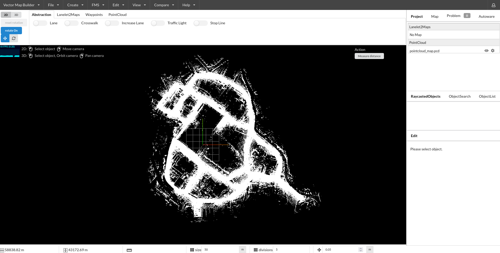
Now, we are ready to create lanelet2 map on our pointcloud map:
- Please click
Create. - Then, click
Create Lanelet2Maps. - Please fill your map name
- Please fill your MGRS zone. (At tutorial_vehicle, MGRS grid zone: 35T - MGRS 100,000-meter square: PF)
- Click
Create.
Creating a simple lanelet#
In order to create a simple lanelet on your map, please follow these steps:
- Click
Lanelet2Mapson the bar - Enable Lanelet mode via selecting
Lanelet. - Then, you can click the pointcloud map to create lanelet.
- If your lanelet is finished, you can disable
Lanelet. - If you want to change your lanelet width, click
lanelet-->Change Lanelet Width, then you can enter the lanelet width.
Video Demonstration:
Join two lanelets#
In order to join two lanelets, please follow these steps:
- Please create two distinct lanelet.
- Select a Lanelet, then press
Shiftand select other lanelet. - Now, you can see
Join Laneletsbutton, just press it. - These lanelets will be joined.
Video Demonstration:
Join multiple lanelets#
In order to add (join) two or more lanelets to another lanelet, please follow these steps:
- Create multiple lanelets.
- You can join the first two lanelets like the steps before.
- Please check end points ids of first lanelet.
- Then you need to change these ids with third lanelet's start point. (Please change with selecting linestring of lanelet)
- You will see two next lanes of the first lanelet will be appeared.
Video Demonstration:
Change the speed limit of a lanelet#
In order to change the speed limit of lanelet, please follow these steps:
- Select the lanelet where the speed limit will be changed
- Set
speed limiton the right panel.
Test lanelets with planning simulator#
After the completing of creating lanelets, we need to save it. To that please click File --> Export Lanelet2Maps then download.
After the download is finished, we need to put lanelet2 map and pointcloud map on the same location. The directory structure should be like this:
<YOUR-MAP-DIRECTORY>/
 ├─ pointcloud_map.pcd
 ├─ lanelet2_map.osm
 └─ map_projector_info.yaml
The map_projector_info.yaml file tells Autoware the projection of the map. Write the MGRS grid that you entered when you created the Lanelet2 map in Vector Map Builder:
projector_type: MGRS
vertical_datum: WGS84
mgrs_grid: <YOUR-MGRS-GRID> # for example, 35TPF
Use the vertical datum of your point cloud map. For a point cloud map from the UTM to MGRS converter, use EGM2008. If the file does not exist, Autoware reads the MGRS grid from the Lanelet2 map. This fallback is deprecated.
If your .osm or .pcd map file's name is different from these names, add the lanelet2_map_file and pointcloud_map_file arguments to the launch command:
ros2 launch autoware_launch planning_simulator.launch.xml map_path:=<YOUR-MAP-FOLDER-DIR> vehicle_model:=<YOUR-VEHICLE-MODEL> sensor_model:=<YOUR-SENSOR-KIT> lanelet2_map_file:=<YOUR-LANELET-MAP-NAME>.osm pointcloud_map_file:=<YOUR-POINTCLOUD-MAP-NAME>.pcd
Now we are ready to launch the planning simulator:
ros2 launch autoware_launch planning_simulator.launch.xml map_path:=<YOUR-MAP-FOLDER-DIR> vehicle_model:=<YOUR-VEHICLE-MODEL> sensor_model:=<YOUR-SENSOR-KIT>
Example for tutorial_vehicle:
ros2 launch autoware_launch planning_simulator.launch.xml map_path:=$HOME/autoware_data/maps/tutorial_map/ vehicle_model:=tutorial_vehicle sensor_model:=tutorial_vehicle_sensor_kit vehicle_id:=tutorial_vehicle
- Click
2D Pose Estimatebutton on rviz or pressPand give a pose for initialization. - Click
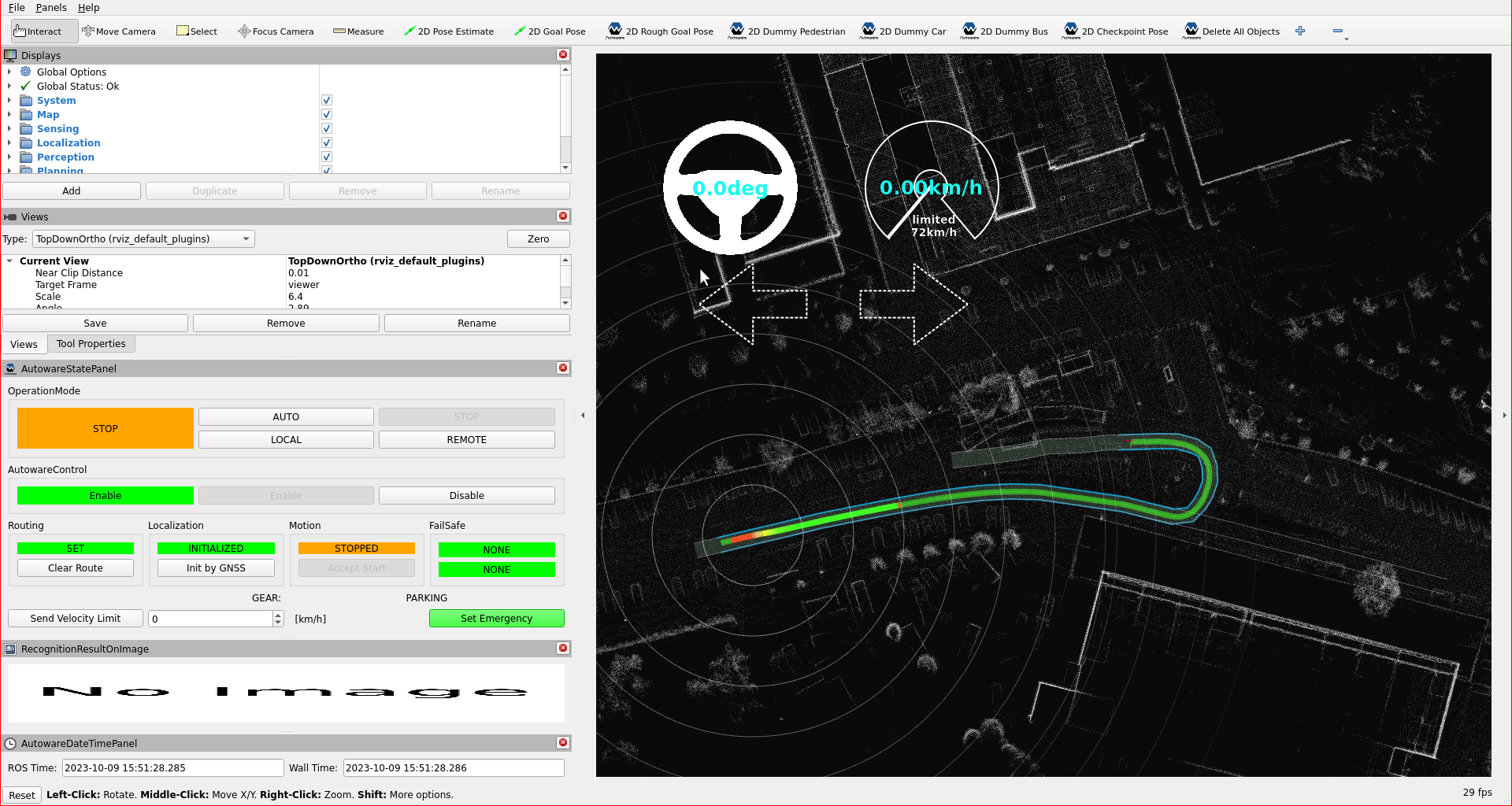
2D Goal Posebutton on rviz or pressGand give a pose for goal point.