Lidar-Lidar calibration#
Overview#
In this tutorial, we will explain lidar-lidar calibration over the mapping-based calibrator of TIER IV's CalibrationTools.
Warning
Please obtain the initial calibration results from the Manual Calibration section. This is crucial for obtaining accurate results from this tool. We will utilize the initial calibration parameters that were calculated in the previous step of this tutorial. To apply these initial values in the calibration tools, please update the calibration files in the config/ folder of your sensor kit description package.
We need a sample bag file for the lidar-lidar calibration process which includes raw lidar topics. Also, we recommend using an outlier-filtered point cloud for mapping because this point cloud includes a cropped vehicle point cloud. Therefore, vehicle points are not included in the map. When you start the bag recording, you should not move the vehicle for the first 5 seconds for better mapping performance. The following shows an example of a bag file used for this calibration:
ROS 2 Bag example of our calibration process for tutorial_vehicle
Files:             rosbag2_2023_09_05-11_23_50_0.db3
Bag size:          3.8 GiB
Storage id:        sqlite3
Duration:          112.702s
Start:             Sep  5 2023 11:23:51.105 (1693902231.105)
End:               Sep  5 2023 11:25:43.808 (1693902343.808)
Messages:          2256
Topic information: Topic: /sensing/lidar/front/pointcloud_raw | Type: sensor_msgs/msg/PointCloud2 | Count: 1128 | Serialization Format: cdr
                   Topic: /sensing/lidar/top/pointcloud | Type: sensor_msgs/msg/PointCloud2 | Count: 1128 | Serialization Format: cdr
Mapping-based lidar-lidar calibration#
The mapping lidar makes a pointcloud map, and the calibrator registers the point clouds of the other lidars to this map. The mapping lidar will be used for mapping purposes, but it will not be calibrated. We can consider this lidar as the main sensor for our hardware architecture. Therefore, other lidars will be calibrated with respect to the mapping lidar (main sensor).
Launching the calibrator#
Source your Autoware workspace and start the sensor calibration manager:
ros2 run sensor_calibration_manager sensor_calibration_manager
Select default_project as the project and mapping_based_lidar_lidar_calibrator as the calibrator, and click Continue. Then set the launch arguments for your sensor kit:
| Argument | Description | Value for tutorial_vehicle |
|---|---|---|
mapping_lidar_frame | The frame of the mapping lidar | rs_helios_top |
mapping_pointcloud | The point cloud topic of the mapping lidar | /sensing/lidar/top/pointcloud |
calibration_lidar_frames | The frames of the lidars to calibrate | [rs_bpearl_front] |
calibration_pointcloud_topics | The point cloud topics of the lidars to calibrate, same order | [/sensing/lidar/front/pointcloud_raw] |
mapping_registrator | The registration method of the mapping: ndt or gicp | ndt |
base_frame | The base frame of the vehicle | base_link |
Click Launch. RViz starts with the calibrator. You can save your RViz configuration for later use.
The calibrator needs the tf of your vehicle and sensors. The bag does not give it, because the command below remaps the tf topics of the bag. In another terminal, publish the tf with tier4_vehicle_launch, as on the manual calibration page:
ros2 launch tier4_vehicle_launch vehicle.launch.xml vehicle_model:=<OWN-VEHICLE-MODEL> sensor_model:=<OWN-SENSOR-KIT> launch_vehicle_interface:=false use_sim_time:=true
Then play ROS 2 bag file:
ros2 bag play <rosbag_path> --clock -r 0.2 \
--remap /tf:=/null/tf /tf_static:=/null/tf_static # if tf is recorded
When the tf frames and the calibration service are available, click the Calibrate button of the sensor calibration manager.
Lidar-lidar calibration process with mapping-based calibrator#
The calibration step consists of two phases: mapping and calibration. At the bag starts playing, then mapping starts as well as the rviz2 screenshot below.
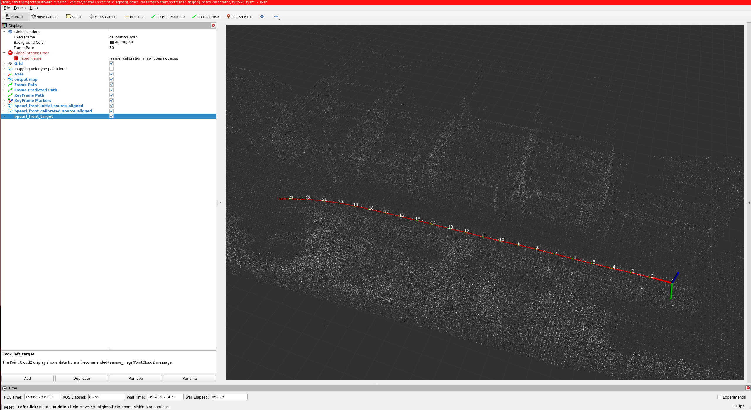
So, red arrow markers indicate poses during mapping, green arrow markers are special poses taken uniformly, and white points indicate the constructed map.
Mapping halts either upon reaching a predefined data threshold or can be prematurely concluded by invoking this service:
ros2 service call /stop_mapping std_srvs/srv/Empty
After the mapping phase of calibration is completed, then the calibration process will start. After the calibration is completed, then you should rviz2 screen like the image below:
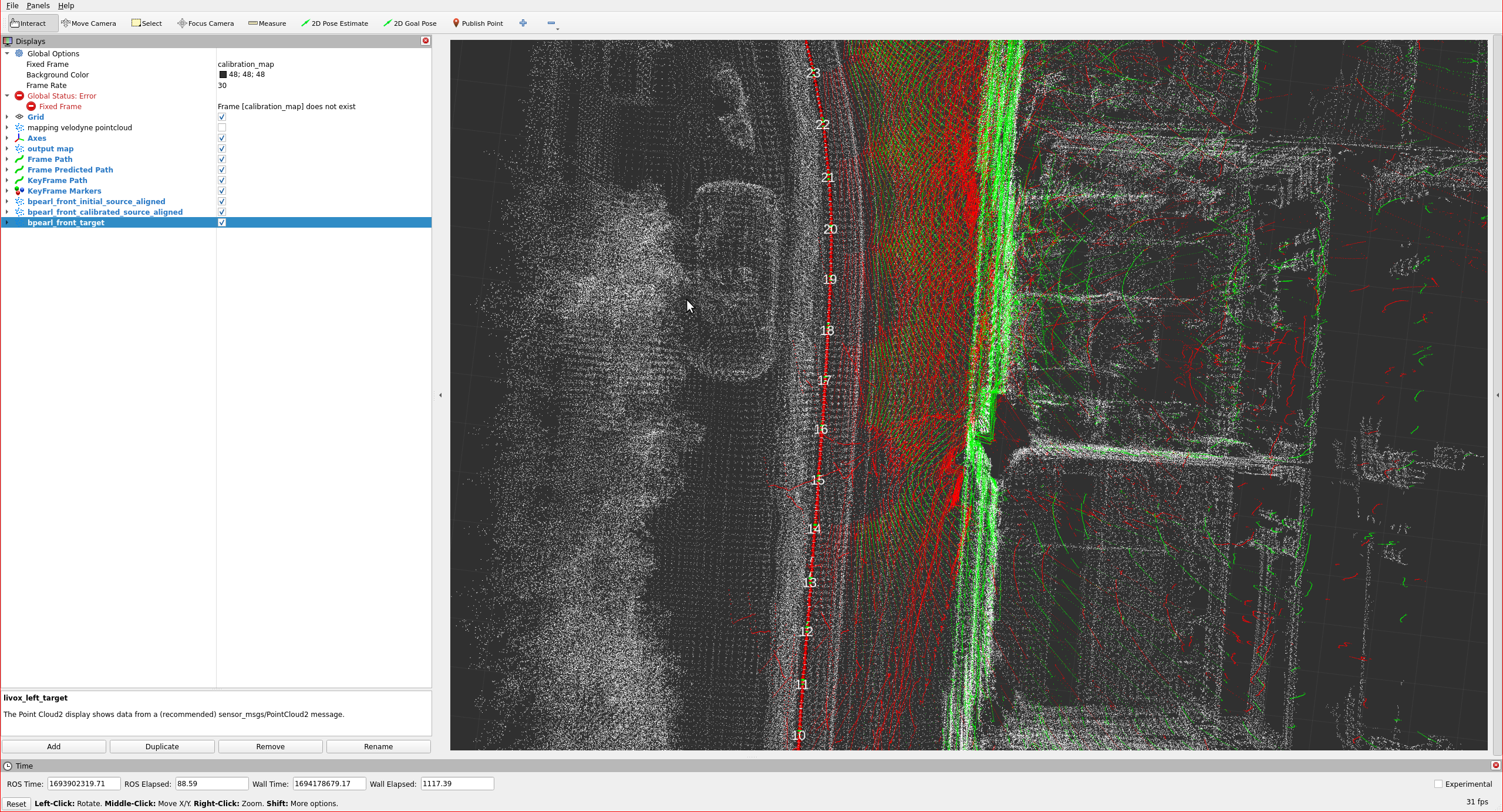
The red points indicate pointcloud that initial calibration results of previous section. The green points indicate aligned point (calibration result).
The sensor calibration manager shows the result in the Calibration tree and Final TF tree widgets. Click Save calibration to save the result to a file. The result is the transformation from mapping_lidar_frame to each lidar in calibration_lidar_frames. Before you write it to sensor_kit_calibration.yaml, convert it to the transformation from sensor_kit_base_link to the base frame of the lidar (for example rs_bpearl_front_base_link). Use the other transformations of your tf tree for this conversion.
Here is the video for demonstrating the mapping-based lidar-lidar calibration process on tutorial_vehicle. The video shows an earlier version of CalibrationTools, so the windows look different.